Why Z values in the .nc file don't match the configured Safe Z
See how the Z Origin Reference setting and the through-cut clearance shift the Z values written into your .nc file so you can tell a correct file from a real depth error.
Clients comparing their .nc file against machine settings often report 'wrong' Z values. Two mechanisms explain nearly all cases. First, the Z Origin Reference setting shifts every emitted Z: with 'bottom_plane' (Z=0 at the machine bed / panel bottom), the retract height equals Safe Z as configured; with 'top_plane' (Z=0 at the top of the panel), every Z is shifted down by the panel thickness, and all values are clamped so they never exceed Safe Z. So with Safe Z = 25 on an 18 mm panel in top-plane mode, retracts appear as Z7.00 (25 minus 18), not Z25.00 - the file is correct, the wire value is just expressed in the machine's Z reference. Second, Through Cut Clearance (labelled 'Addition cut depth for Through/Panel cut (mm)' in the machine settings, default 0.1) converts surface-level cuts into slightly-past-surface cuts: any target Z within a hair of 0 is replaced by minus the clearance (e.g. -0.10), and the clamp range extends that far below the reference plane. So cut depths like Z-18.10 on an 18 mm panel in top-plane mode mean clearance 0.1, not a depth error. Diagnostic rule: the maximum G0 Z in the file equals the effective safe height; the minimum Z should never be more negative than panel thickness plus through-cut clearance. Match the Z reference setting to the machine's fixture convention (most flat-table nesting machines: bottom_plane).
In the MES app's nesting NC machine settings the fields are labelled 'Maximum Safe Z' (default 25) and 'Z Origin Reference' (default Bottom Plane), and the cut-depth extension field is 'Addition cut depth for Through/Panel cut (mm)'; there is no field named 'Through Cut Clearance'.
✓ Checked in the product on 18 October 2026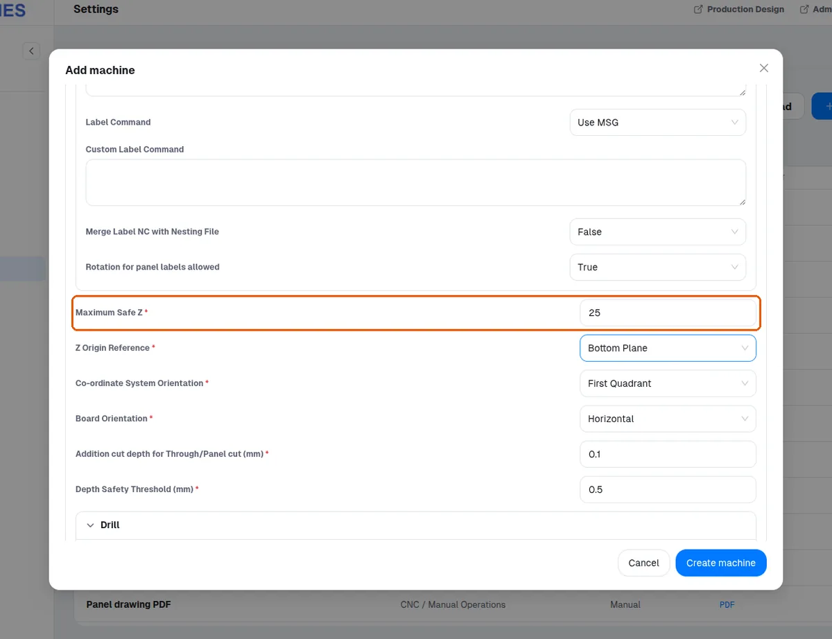
On nesting NC (and SCM) machines, the router settings offer approach/retract (lead-in/lead-out) strategies with a configurable distance. Clients sometimes report that lead-in is switched on but the generated program plunges straight into the contour. This is expected behavior of a safety clamp, not a lost setting: before adding the lead-in, Infurnia limits the effective distance to the smaller of (a) the configured approach/retract distance, (b) the available tool clearance (maximum tool width minus tool diameter minus 0.5 mm), and (c) the distance to the next point on the contour minus the tool diameter. If the clamped result comes out at effectively zero (below 0.01 mm), the lead-in or lead-out is simply not added - with no warning anywhere in the UI or the file. The common real-world causes are small parts (contour segments shorter than the tool diameter) and wide tools with little clearance margin. What to check with the client: the tool's diameter and width in the tool list (clearance is width minus diameter minus 0.5), the size of the affected parts, and whether only some contours lack lead-ins (typical - large parts get them, small ones don't). Reducing the configured distance will not help if the clearance term is the binding one; the practical fixes are a narrower tool or accepting vertical plunge on small parts.